|
|
|
The original mustang turn
signal/hazard/parking lights/headlights circuits seemed way to
complicated so I decided to replace them. I also wanted
to use dash mounted toggle switches instead of the bulky mustang
units. I stumbled across Engineer Ed's black box on the
cobraforum and decided to make one. It basically simplifies the
entire illumination system of the car and makes it so if
something goes wrong electrically, you can actually figure out
how to fix it. I spent at least a week going from buzzer to
flasher to relay to day/light illumination etc. and i still couldn't
figure out how the original system worked. I spent a good three weeks on
the new box (only because I didn't
know a relay from a diode and I had never done anything
electrical before). If I were to do it again I could do it in
about two days. I'm going to show you how to do the same. I just
hope you have a radio shack nearby...In the end, my physical
black box only contained the turn signal circuit. But, I still
used all the relays from the schematic, I just didn't mount them
in a box. So this is actually only a how-to
on the actual box that I made. Did I mention the black box also
eliminates about 1/10th of the wiring in the
car!
NOTE: Please read the
whole page before you decide to do this. Actually using the box
requires extensive work to your wiring harness and a good
understanding of which wires go where in the harness. Don't even
try it without a wiring diagram for your year.
|
|
Click Pictures to
Enlarge |
 |
 |
|
| The
best way to make the turn signal circuit is to make a circuit
board, mount it in a metal box and connect it up to your
existing wiring. Its cheap, easy, fun, and basically
unbreakable. |
Go
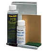
to radio shack and get their pc board kit(276-1576). Its like
$14 and comes with everything you need except the relays and
diodes. You will need to special order the relays(900-2398). The
diodes(276-1101) you can pick up at the store-50V 1 amp. Get
four (a couple extra don't hurt). I used a 2 3/8 X 2 1/8 X 1 5/8
aluminum project enclosure(270-235) but you can use anything you
find there that will fit. For connectors I used the nylon 12 pin
male and female connectors they sell at every rs store. |
Actually
making the circuit board is a matter of following the directions
with the kit and following my included schematic. A couple of
notes: Before you start, trim the board to fit in your box. Mine
was 3.25" X 2.75". I also drilled the
holes before I etched even though the directions have you drill
after. I used trace paper and cut out a rectangle the same size
as the board. I traced the circuit with a pencil, taped the trace
paper over the board, and drilled the holes through the paper
into the board.. |

|

|

|
| After
you etch and clean it you should look something that looks like
this. You can then solder in the two relays and the four diodes
like the picture shows. Make sure to test all of your pathways
to make sure none touch. Also, make sure your diodes are
going in the right direction. I put one in backwards and it was
a pain to desolder and flip it around. |
Next
solder the wires to the drilled holes. Cut all the wire the same
length so you keep it neat. I labeled all of them with
numbers. |
Finally,
you will have to figure out some way to connect the wires from
your box to your harness. I couldn't find many connectors around
so i had to make a way to connect the rectangular radio shack
connectors to the side of the box. This picture shows how I did
it. I simply found a piece of scrap aluminum, cut out a square
the same size as the connector, then drilled a circular hole in
the box and mounted it. The picture describes it better. |
 |
 |
|
| I used
some press lock strips to secure the board to the box, but
superglue works fine too. Once its secured, you can connect the
wires to the connector and close up the box. |
I
installed the box on top of the pedal box with some more press
lock strips. After I ripped out most of the original turn signal wiring
from the harness, I found all the wires I needed and
connected them with the male side of the 12 pin connector. |
Click Here for More Wiring Pictures! |
| SOURCES |
|
|
| Turn Signal Circuit Board Schematic |
Black Box Schematic |
Wiring Diagram
For My car |
| PARTS
LIST |
|
|
| 1.)
1 -- PC board kit -- 276-1576 -- 13.99 |
| 2.)
2 -- Special order Relay -- 900-2398 -- 1.99 each |
| 3.)
4 -- 50V diode -- 276-1101 -- .49 for 2 |
| 4.)
1 -- Aluminum Project Enclosure -- 270-235 - 1.99 |
| 5.)
2 -- Male and Female Molex 12 pin connector -- 1.99 each |